To configure your F5 firewall and integrate it with the Glasswall Halo ICAP server, please follow this configuration guide.
Note: these steps are documented as per F5 version BIG-IP 17.1.1.3 Build 0.0.5 Point Release 3.
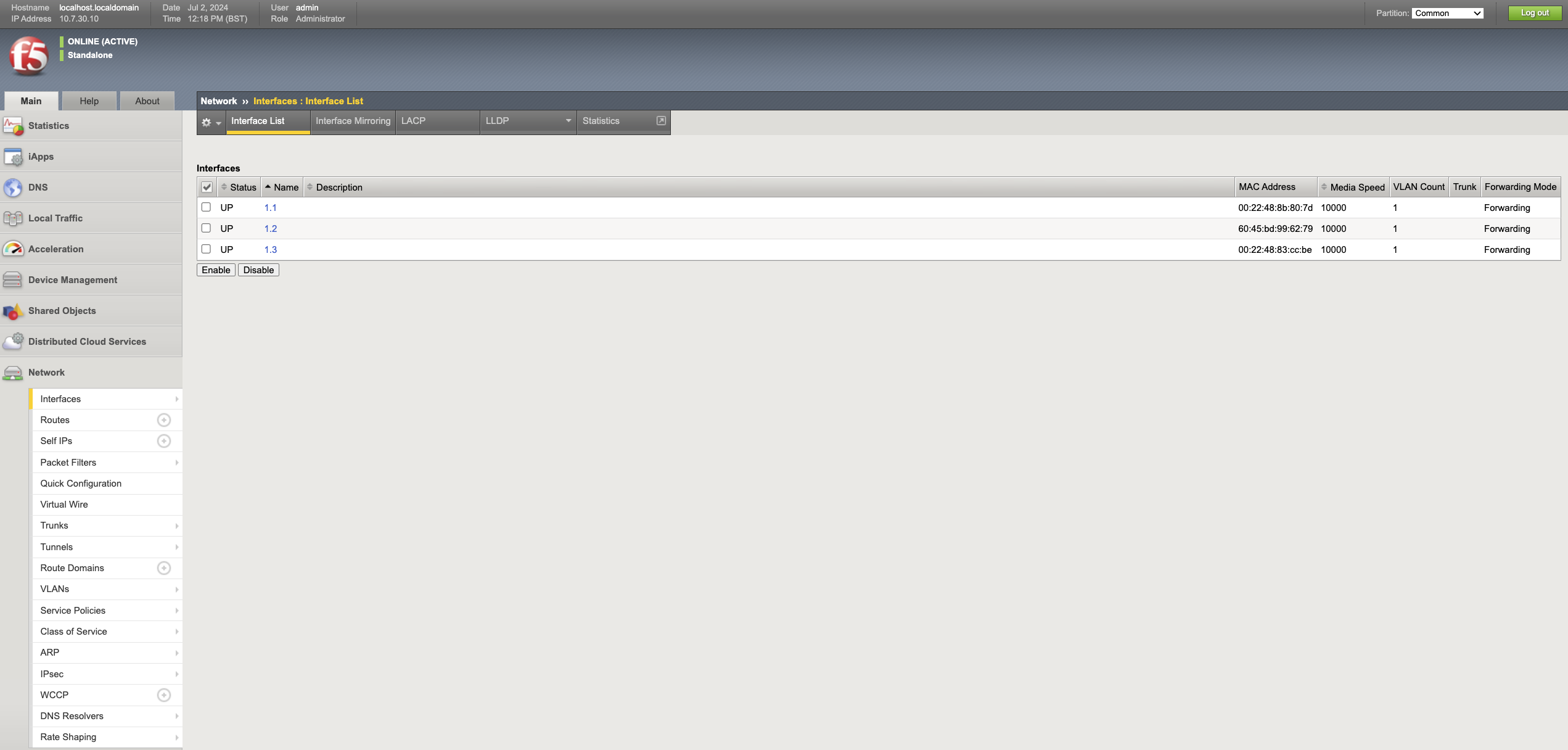
Configure Interfaces and Routes
- Before configuring the Interfaces, ensure you can see 3 Interfaces under Network -> Interfaces -> Interface List.
- Note: this shows the data plane Interfaces and does not include management interface.
- The names of the Interfaces will be 1.1, 1.2, 1.3.
- Based on the MAC address of each Interface by comparing it with the MAC address on the Interfaces attached to the firewall VM, note down which subnets each Interface belongs to.
- In the Dev environment:
1.1belongs toinside subnet1.2belongs tooutside subnet1.3belongs toicap subnet.
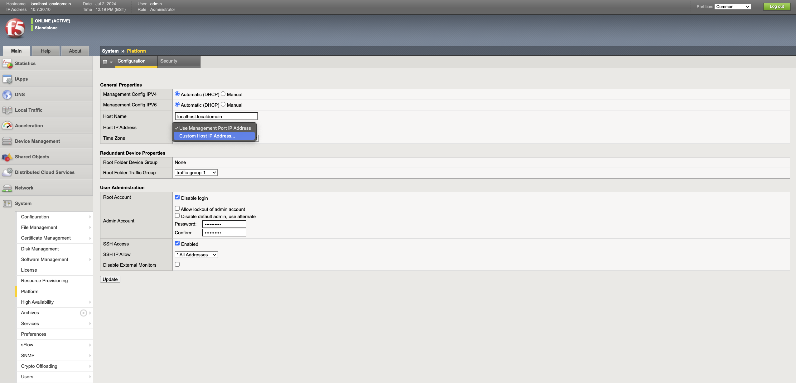
1 - Configure Management IP address
Typically the first interface attached to the firewall is configured as the management interface. If for any reason the management UI is running on a different interface (IP address), follow these steps to change the Management IP address.
- Login to the F5 Admin Portal.
- Navigate to System -> Platform.
- Under the Host IP Address drop-down, select Custom Host IP Address and enter the new IP.
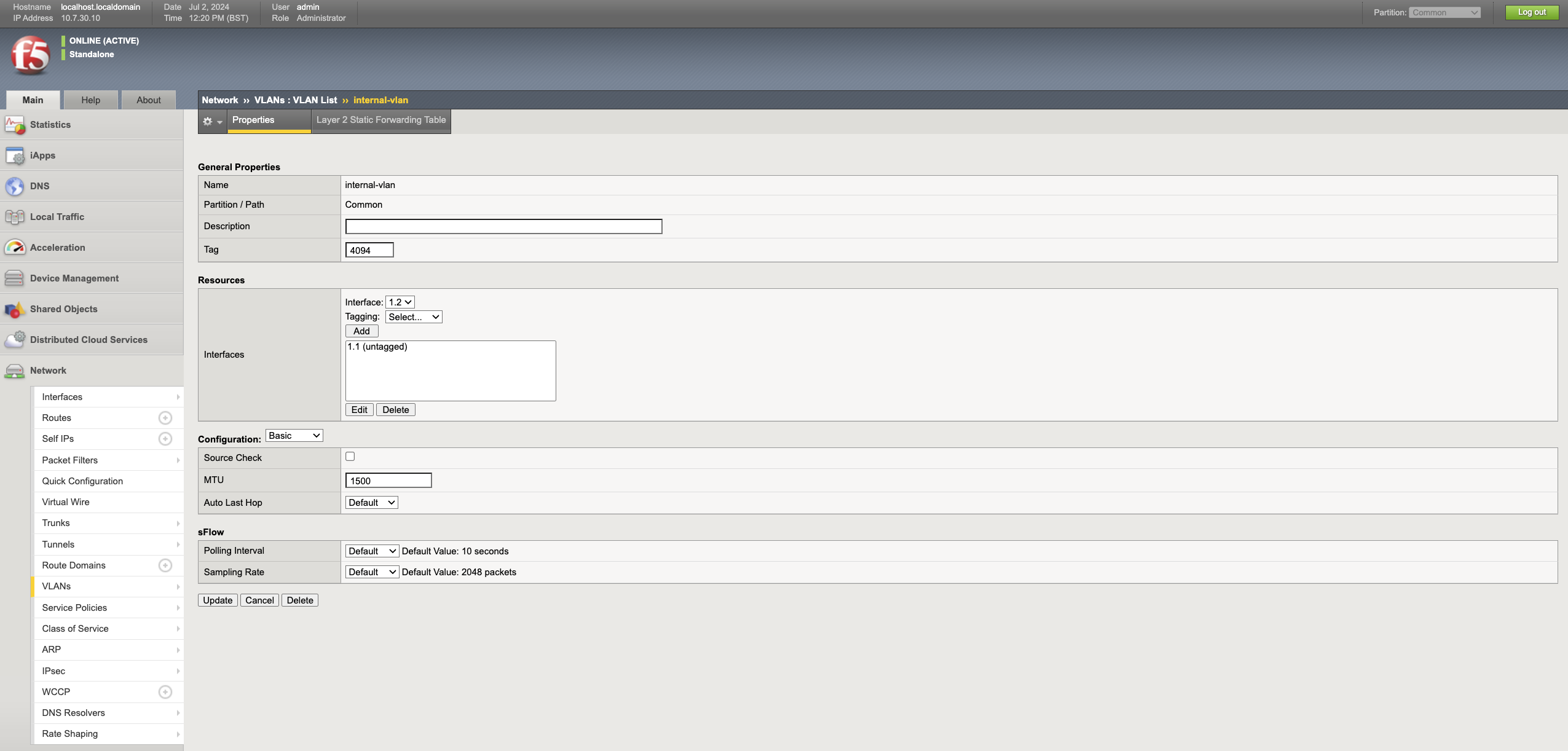
2 - Configure inside interface
- Navigate to Network -> VLANs -> VLANs List and click Create.
- Enter the name as
inside-vlan. - Select the inside interface from the drop-down and click Add.
Note: the interface names will be1.1,1.2and1.3. In the previous step, the sub-net to which the interface belongs to, based on the MAC Address is noted down. - Click Finished.
- Navigate to Network -> Self IPs and click Create.
- Enter the name as
inside-ip, and enter the IP Address and Netmask of the inside interface. - Select the
inside-vlanfrom the VLAN drop-down and click Finished.
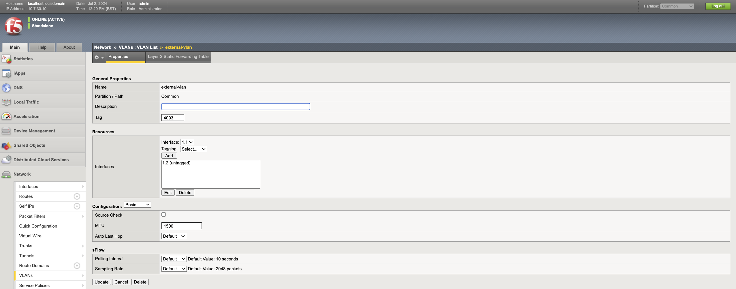
3 - Configure outside interface
- Navigate to Network -> VLANs -> VLANs List and click Create.
- Enter the name as
outside-vlan. - Select the outside interface from the drop-down and click Add.
- Click Finished.
- Navigate to Network -> Self IPs and click Create.
- Enter the name as
inside-ip, and enter the IP Address and Netmask of the outside interface. - Select the
outside-vlanfrom the VLAN drop-down and click Finished.
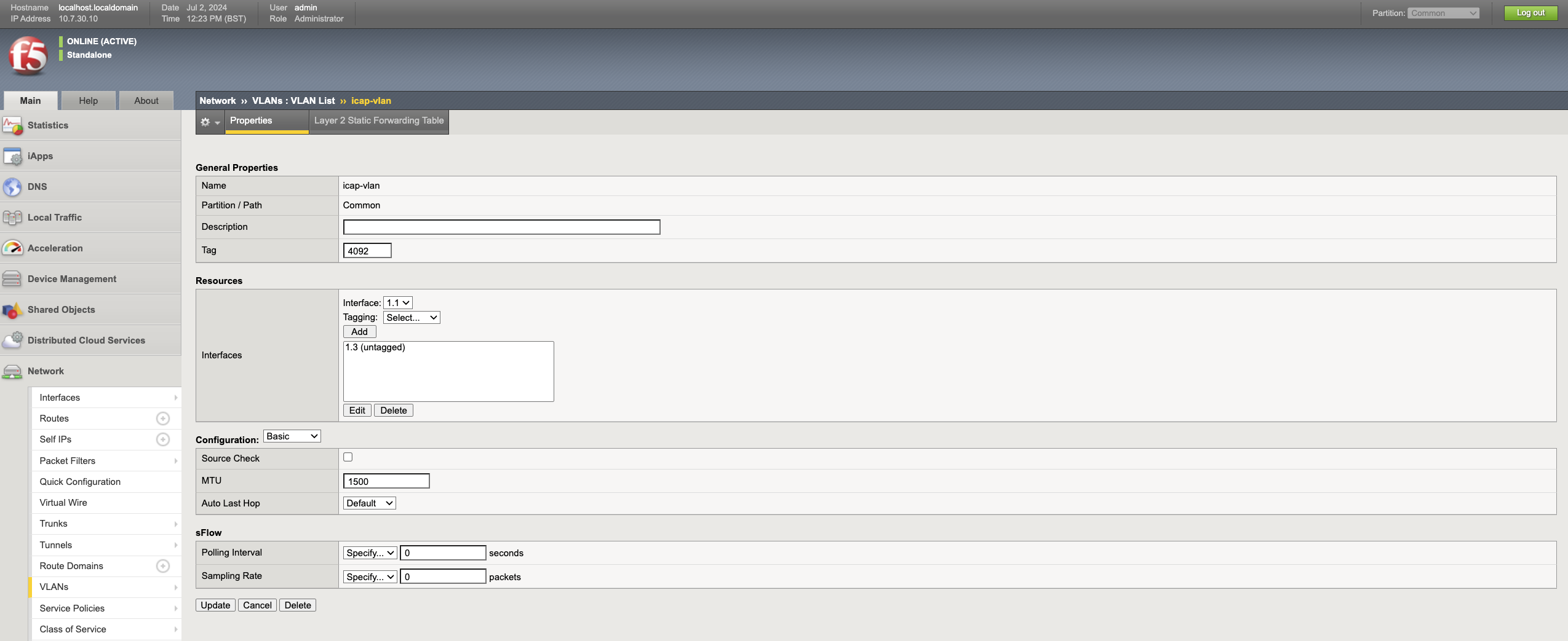
4 - Configure ICAP interface
- Navigate to Network -> VLANs -> VLANs List and click Create.
- Enter the name as
icap-vlan. - Select the ICAP interface from the drop-down and click Add.
- Click Finished.
- Navigate to Network -> Self IPs and click Create.
- Enter the name as
icap-ip, and enter the IP Address and Netmask of the icap interface. - Select the
icap-vlanfrom the VLAN drop-down and click Finished.
ICAP Integration
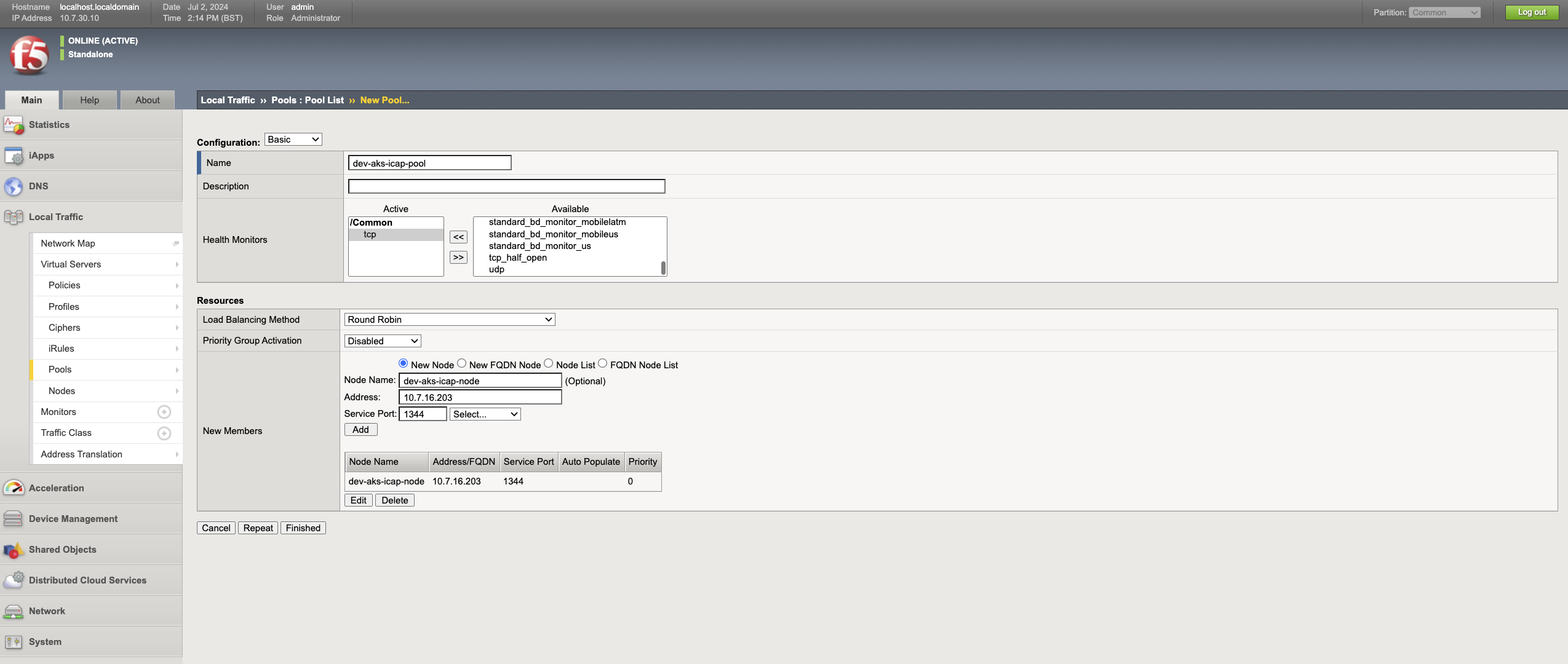
1 - Create ICAP Pool.
The ICAP pool represents a pool of ICAP servers.
- Navigate to Local Traffic -> Pools and click Create.
- Enter an appropriate name and description; e.g. Name -
dev-aks-icap-pool, Description -ICAP Pool for Dev AKS env. - Under Health Monitors, select
tcpfrom the Available column and move it to the Active column. - Enter an appropriate Node Name. e.g.
dev-aks-icap-node. - Enter the IP address of ICAP server, Service Port as
1344and click Add. - Click Finished to save the configuration. If the health checks are successful, the status will appear in green, otherwise red.
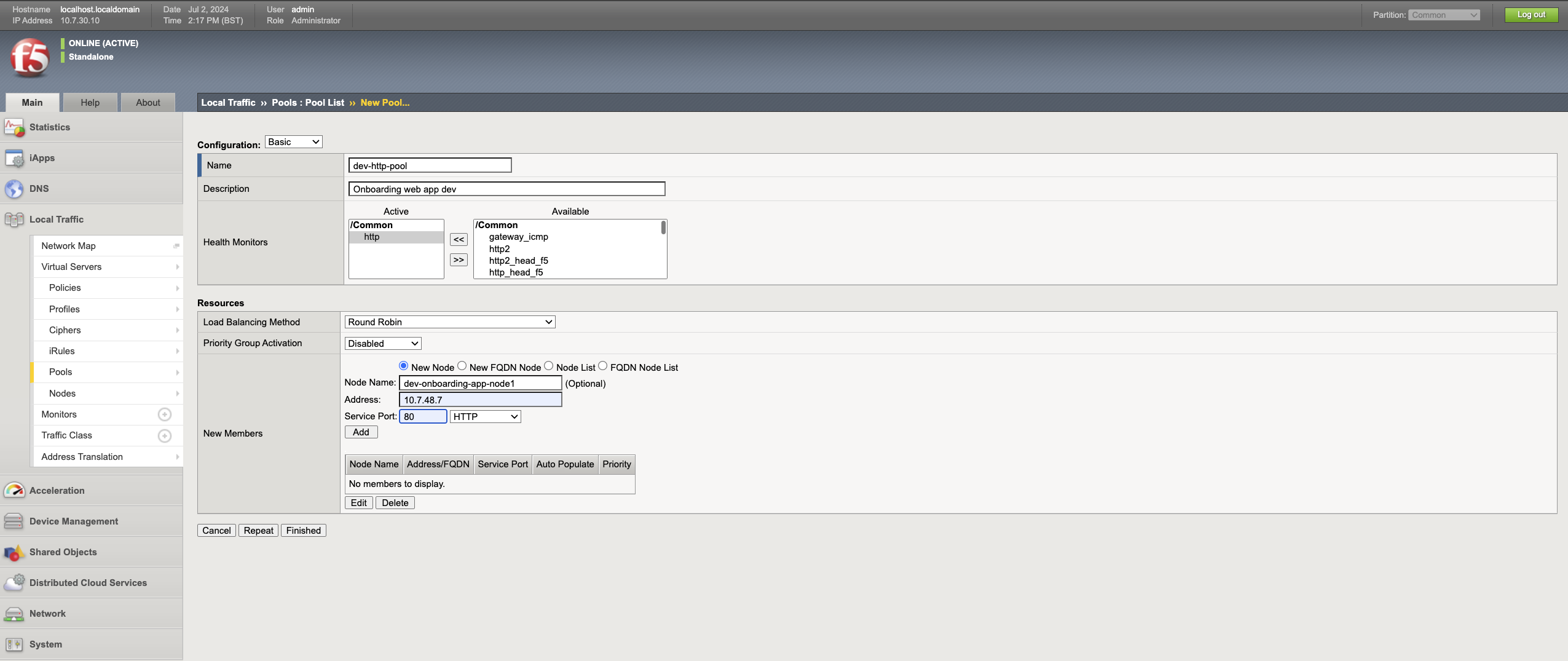
2 -Create HTTP Pool
The HTTP pool represents a pool of web servers that needs to be protected by the F5.
- Navigate to Local Traffic -> Pools and click Create.
- Enter an appropriate name and description. e.g. Name -
dev-http-pool, Description -Onboarding web app dev. - Under Health Monitors, select
httpfrom the Available column and move it to the Active column. - Enter an appropriate Node Name. e.g.
dev-onboarding-app-node1. - Enter the IP address and port of the web server, and click Add.
- Click Finished to save the configuration. If the health checks are successful, the status will appear green, otherwise red.
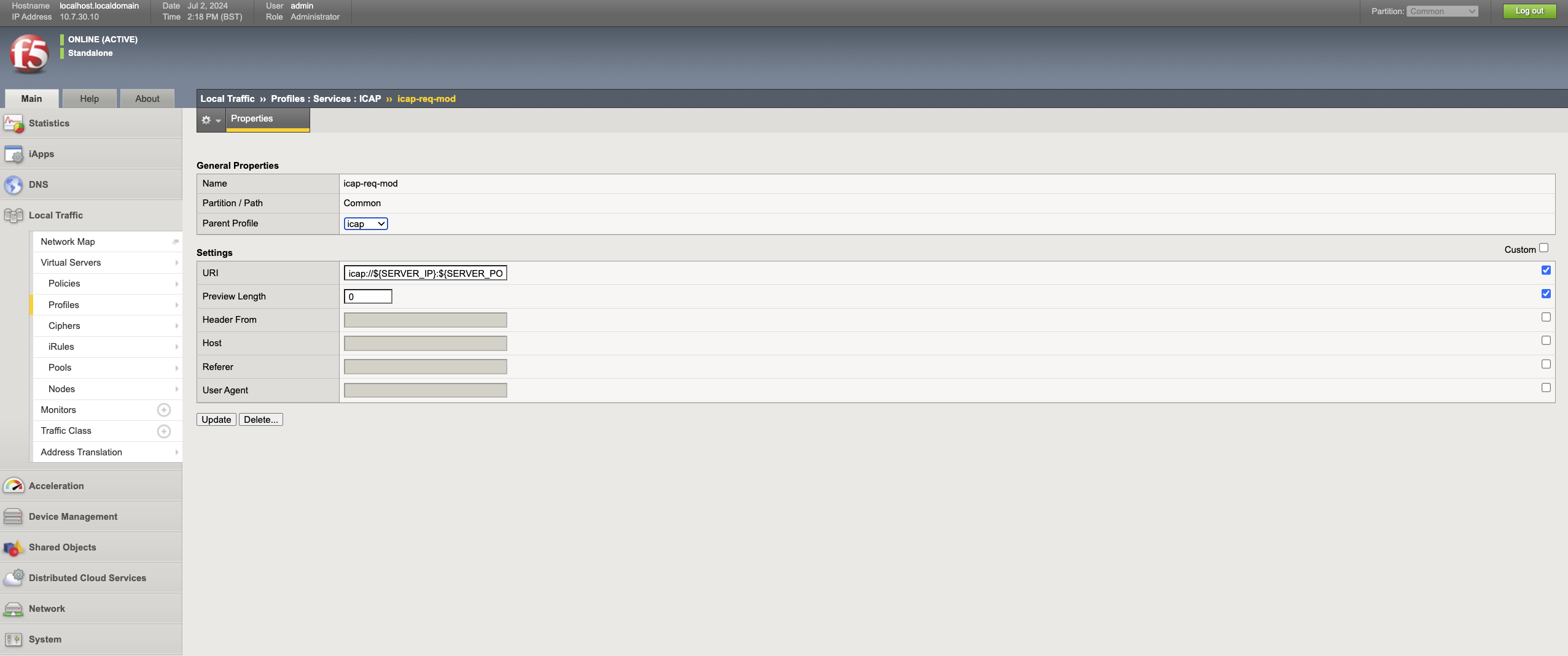
3 - Create ICAP profile
ICAP profile is used to send the traffic from http virtual server to ICAP server to CDR the content. In this scenario as we want to process the files uploaded to web server, we need to use Request modification service in the ICAP.
- Navigate to Local Traffic -> Profiles -> Services -> ICAP and click Create.
- Enter an appropriate name. e.g.
dev-icap-req-mod. - Select icap as the Parent Profile.
- Select the Custom box in Settings and enter
icap://${SERVER_IP}:${SERVER_PORT}/req-cdr-service?profile=defaultin the URL. You can use a custom ICAP profile if needed. - Complete the other fields as required and click Finished.
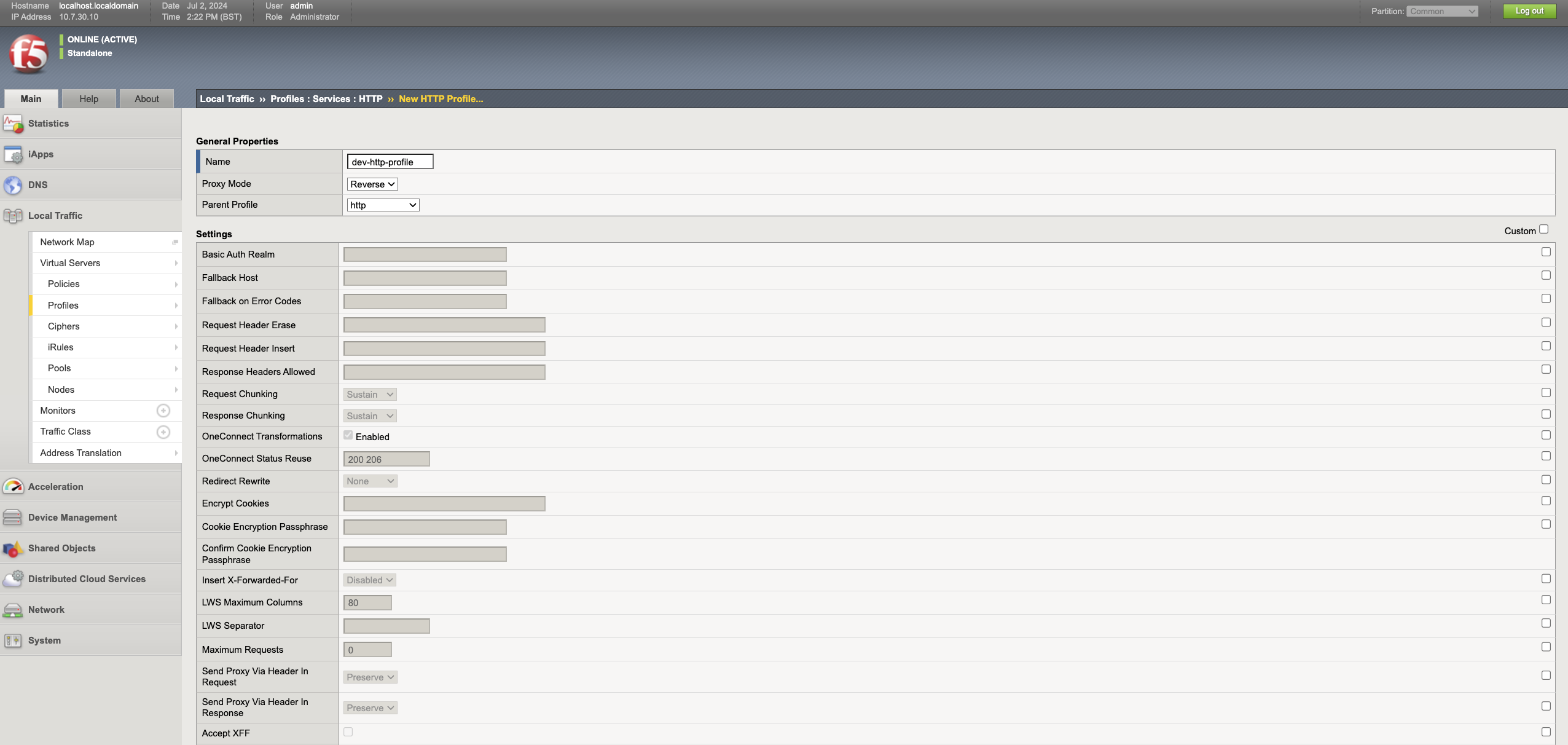
4 - Create HTTP profile
A custom HTTP profile can be used to modify the HTTP traffic of the web server.
- Navigate to Local Traffic -> Profiles -> Services -> HTTP and click Create.
- Enter an appropriate name. e.g.
dev-http-profile. - Select http as the Parent Profile.
- Select the Custom box on the Settings and customise the settings as required.
- Click Finished to save the profile.
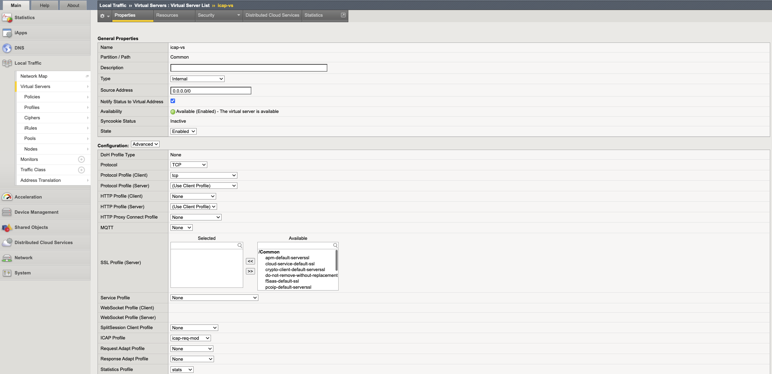
5 - Create ICAP internal virtual server
An internal virtual server is a special type of virtual server used to send the traffic to ICAP server. The ICAP virtual server sits in front of the ICAP pool.
- Navigate to Local Traffic -> Virtual Servers -> Virtual Servers List and Create.
- Enter an appropriate name and description. e.g.
dev-icap-vs. - Select Type as
Internaland enter0.0.0.0/0as the source address. - Select
Advancedconfiguration and under ICAP Profile, select the ICAP profile created in Step 3. - Under
Default Pool, select the ICAP pool created in Step 1. - Click Finished to save the virtual server.
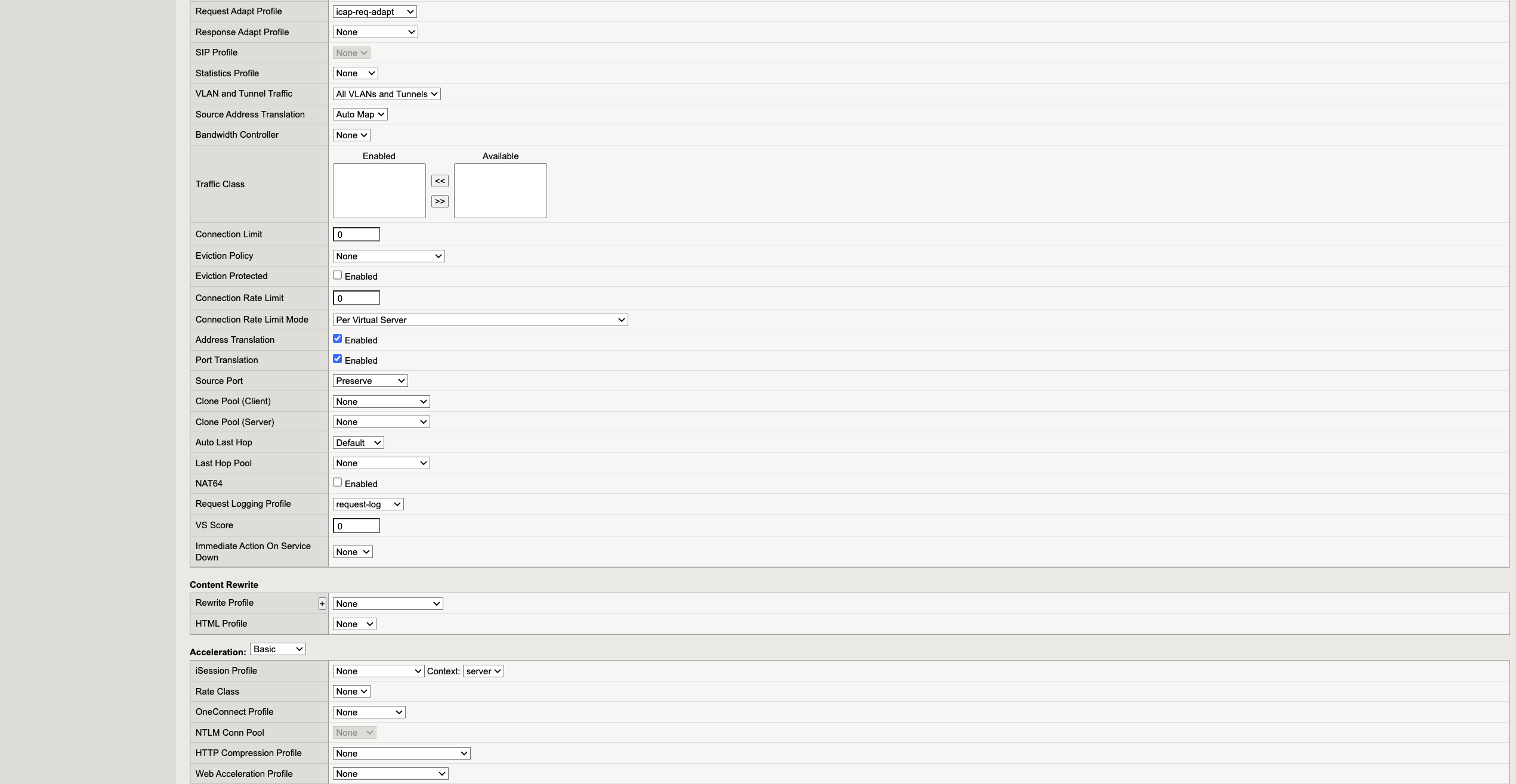
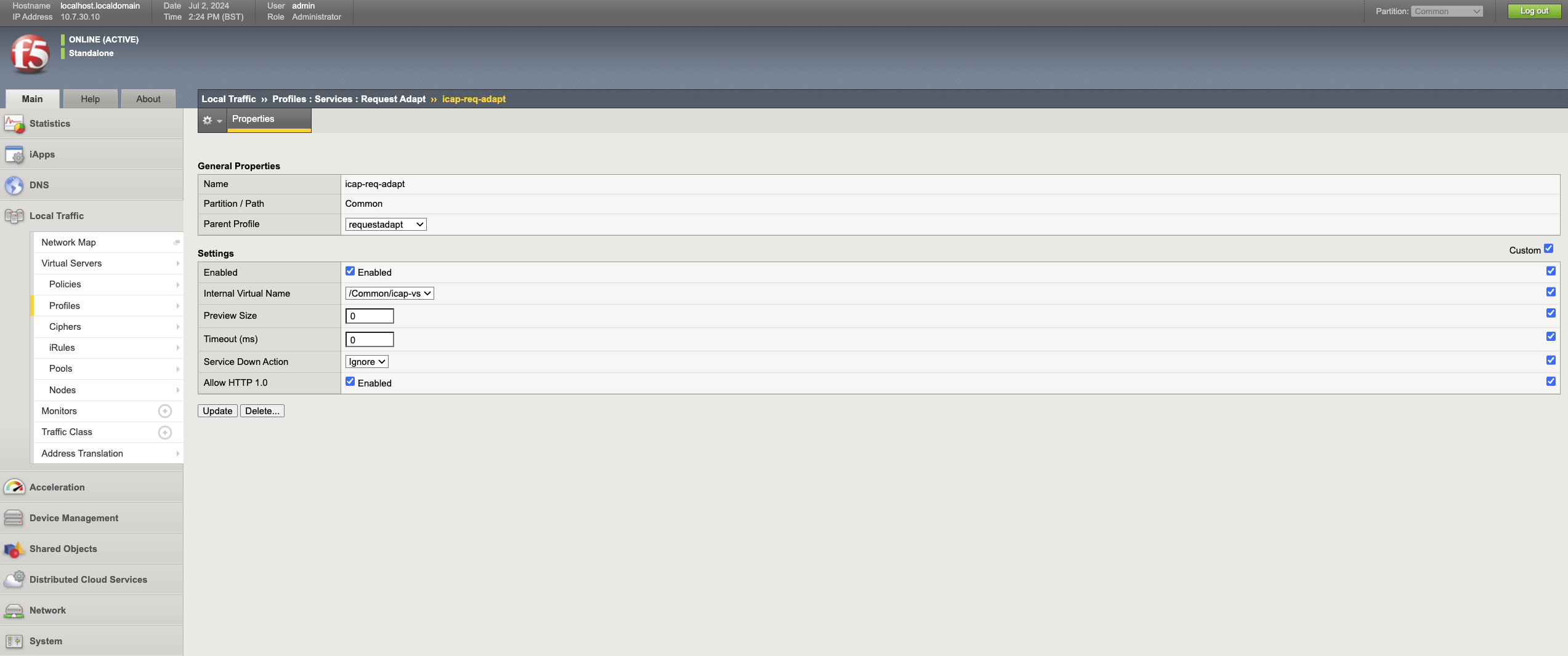
6 - Create Request Adapt profile
- Navigate to Local Traffic -> Profiles -> Services -> Request Adapt and click Create.
- Enter an appropriate name. e.g.
dev-icap-req-adapt. - Under the Parent profile, select
requestadapt. - Select the Custom box in Settings, and select the internal ICAP virtual server created in Step 6 in the Internal Virtual Name drop-down.
- Select the service down action as needed. This represents what action will be taken when the ICAP server is down.
Drop: To drop the traffic at the http virtual server.Reset: Resets the connection on the client side.Ignore: Sends the original traffic to the web server.
- Click Finished to save the request adapt profile.
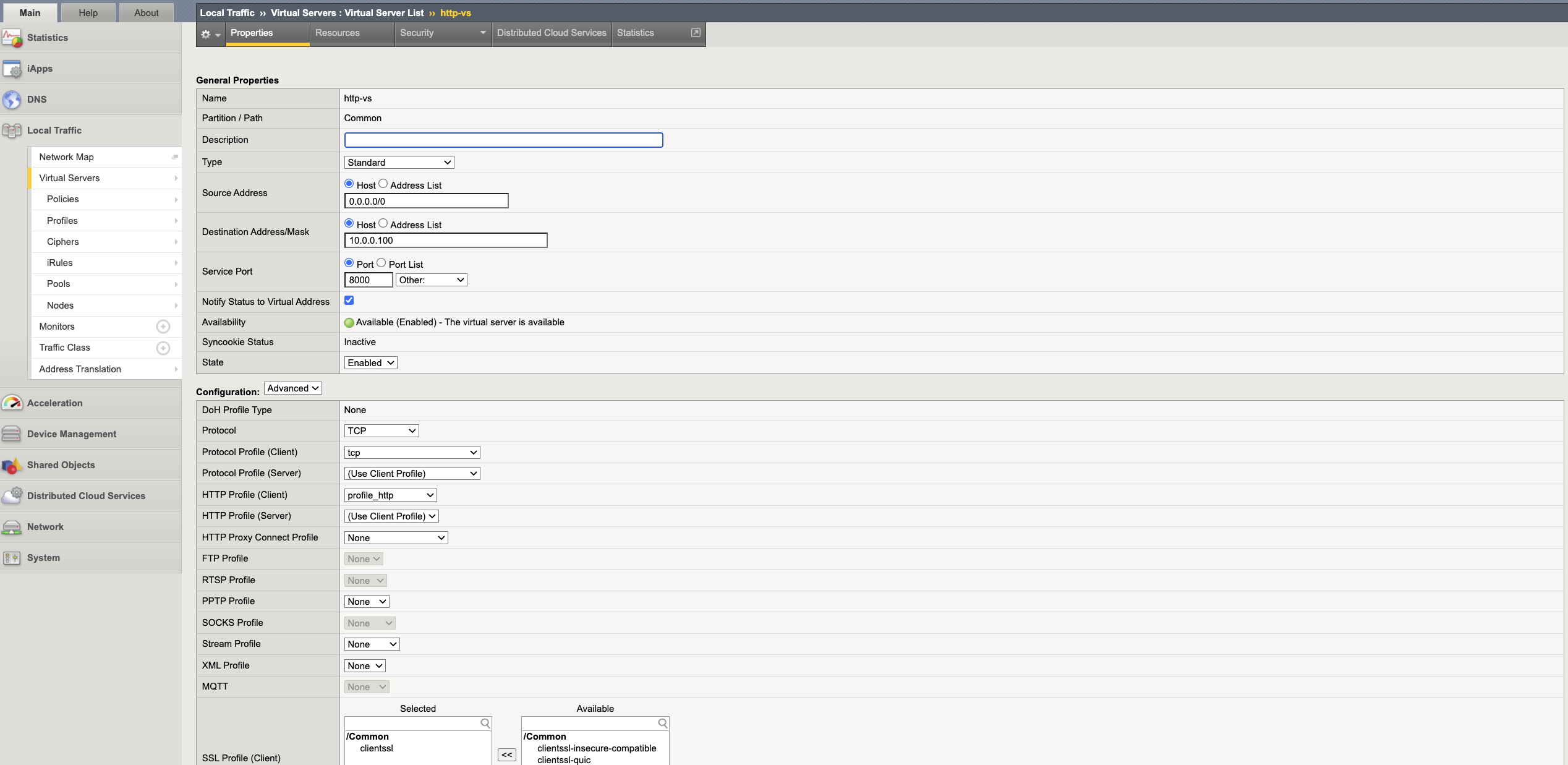
7 - Create HTTP virtual server
A HTTP virtual server sits in front of HTTP pool and provides a virtual IP address that can be used by the users to access the protected web server.
- Navigate to Local Traffic -> Virtual Servers -> Virtual Servers List and click Create.
- Enter an appropriate name. e.g.
dev-onboarding-http-vs. - Enter
0.0.0.0/0in the Source Address. - Choose an IP address for the HTTP virtual server that does not conflict with any other address space and enter it as the destination address.
- Enter the web server port as the Server Port.
- Select Advanced configuration and select HTTP profile created in Step 4 under
HTTP Profile(Client). - Select the request adapt profile created in Step 6 under Request Adapt Profile.
- Select Auto Map under the Source Address Translation drop-down.
- Select the HTTP pool under Default Pool and click Finished.